
Are you looking for a formula relevant for your structural design? Just ask our AI chatbot Mia!
Mia shows you the right formula, with explanations, if necessary.
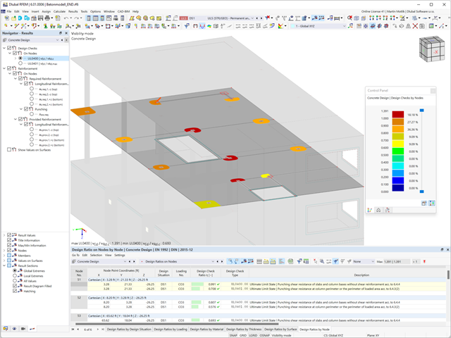
Is the design completed? Then sit back. Because the punching checks are presented for you clearly and with all result details. This allows you to precisely follow each result. The program shows you the provided and allowable shear stresses for the shear resistance of the slab in detail.
RFEM has even more to offer in this add-on. In the next result window, it lists the required longitudinal or punching reinforcement of each analyzed node. You can also find an explanatory graphic there. RFEM shows you the design results clearly displayed with values in the work window. You can integrate all result tables and graphics into the global printout report of RFEM. Thus, you can be sure of a clear documentation.
- Planar and geodesic cutting lines
- Flattening of double-curved surface parts of tensioned membranes or pneumatic cushions
- Definition of cutting patterns by using boundary lines which are not required to be connected
- Sophisticated flattening based on the minimum energy theory
- Welding and boundary allowances
- Uniform or linear compensation in warp and weft direction
- Possibility of different compensations for boundary lines
- Adaptable data organisation (any additional modification of input data is considered up to the final "weld")
- Graphical display of cutting patterns
- Statistical information about each cutting pattern (width, length, size)
- Option to automatically generate cutting patterns from cells

In accordance with DIN 18800, Part 2, the designs are carried out separately for flexural buckling and lateral-torsional buckling to simplify the calculation. Generally, the flexural buckling design is performed in the framework plane using the stress analysis of the planar structure according to the second-order analysis, considering design loads and pre-deformations.
The lateral-torsional buckling design is performed on an individual member detached from the entire structure by using defined boundary conditions and loads in accordance with the elastic-elastic method.
RF-/FE-LTB searches for the governing failure mode by means of the critical load factor which describes flexural, torsional, and lateral-torsional buckling, or the combination of all failure modes, depending on the model and load applied. Then, the module performs recalculation to obtain the required operands.
Detail settings control whether the critical load factor is calculated due to loss of stability (providing the material is defined by infinitely elastic properties), or with stress limitation.
If necessary, you can adjust the size of the finite elements. You can also modify the partial safety factor γM. In RF-/FE-LTB, iteration parameters are preset appropriately to calculate all common models, but can be adjusted individually.
- Integration in RFEM/RSTAB with automatic geometry recognition and transfer of internal forces
- Optional manual definition of connections
- Extensive library of hollow sections for chords and struts:
- Round sections
- Square sections
- Rectangular sections
- Implemented steel grades: S 235, S 275, S 355, S 420, S 450, and S 460
- Various types of connections available, depending on the standard specifications:
- K connection (gap/overlapping)
- KK connection (spatial)
- N connection (gap/overlapping)
- KT connection (gap/overlapping)
- DK connection (gap/overlapping)
- T connection (planar)
- TT connection (spatial)
- Y connection (planar)
- X connection (planar)
- XX connection (spatial)
- Selection of partial safety factors according to the National Annex for Germany, Austria, Czech Republic, Slovakia, Poland, Slovenia, Switzerland, or Denmark
- Adjustable angles between struts and chords
- Optional chord rotation of 90° for rectangular hollow sections
- Consideration of gaps between struts or overlapping struts
- Optional consideration of additional nodal forces
- Design of the connection as the maximum load-bearing capacity of the struts of a truss for axial forces and bending moments
The nonlinear calculation adopts the real mesh geometry of planar, buckled, simple curved, or double curved surface components from the selected cutting pattern and flattens this surface component in compliance with the minimization of distortion energy, assuming defined material behavior.
In simplified terms, this method attempts to compress the mesh geometry in a press, assuming frictionless contact, and to find the state in which the stresses from flattening in the component are in equilibrium in the plane. This way, minimum energy and optimum accuracy of the cutting pattern are achieved. Compensation for warp and weft as well as compensation for boundary lines are considered. Then, the defined allowances on boundary lines are applied to the resulting planar surface geometry.
Features:
- Minimization of distortion energy in the flattening process for very accurate cutting patterns
- Application for almost all mesh arrangements
- Recognition of adjacent cutting pattern definitions to keep the same length
- Mesh application for main calculation
.png?mw=640&hash=53c64389797699e939283ddbfc3d88485fcbfbf5)
- Full integration in RFEM/RSTAB, including import of all relevant loads
- General stress analysis with warping torsion according to elastic-elastic method
- Stability analysis of planar continuous members for buckling and lateral-torsional buckling
- Determination of critical load factor and thus of Mcr or Ncr (the factor can be used in RF-/LTB for the el/pl design)
- Lateral-torsional buckling analysis of any cross-section (also the SHAPE-THIN cross-sections)
- Design of members and sets of members with applied torsion (for example, crane girder)
- Optional determination of the limit load factor (critical load factor)
- Display of eigenmodes and torsional modes on the rendered cross-section
- Wide range of tools for determining shear panels and rotational restraints (such as corrugated sheets, purlins, bracings)
- Easy determination of discrete springs such as warp springs from end plates or rotational springs from columns
- Graphical selection of load application points on a cross-section (upper chord, centroid, lower chord, or any other point)
- Free arrangement of eccentric nodal and line supports on a cross-section
- Determination of value for inclination or precamber by means of eigenvalue analysis
- Special warping releases applicable for definition of warping conditions on transitions

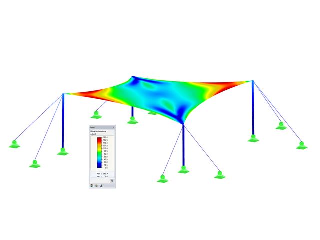
Do you know exactly how the form-finding is performed? First, the form-finding process of the load cases with the load case category "Prestress" shifts the initial mesh geometry to an optimally balanced position by means of iterative calculation loops. For this task, the program uses the Updated Reference Strategy (URS) method by Prof. Bletzinger and Prof. Ramm. This technology is characterized by equilibrium shapes that, after the calculation, comply almost exactly with the initially specified form-finding boundary conditions (sag, force, and prestress).
In addition to the pure description of the expected forces or sags on the elements to be formed, the integral approach of the URS also enables a consideration of regular forces. In the overall process, this allows, for example, for a description of the self-weight or a pneumatic pressure by means of corresponding element loads.
All these options give the calculation kernel the potential to calculate anticlastic and synclastic forms that are in an equilibrium of forces for planar or rotationally symmetric geometries. In order to be able to realistically implement both types individually or together in one environment, the calculation provide you with two ways to describe the form-finding force vectors:
- Tension method - description of the form-finding force vectors in space for planar geometries
- Projection method - description of the form-finding force vectors on a projection plane with fixation of the horizontal position for conical geometries
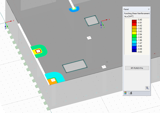
After the design, the punching checks are presented clearly and with all result details, so that traceability is guaranteed at all times. The provided and allowable shear stresses for the shear resistance design of a slab as well as various perimeters and reinforcement ratios are represented in detail. If necessary, a clarifying note is displayed.
The next result window lists the required longitudinal or punching reinforcement of each analyzed node. An explanatory graphic is also available. The design results can be clearly displayed with values in the work window. Furthermore, you can add all result tables and graphics into the global printout report of RFEM, which guarantees coherent documentation.

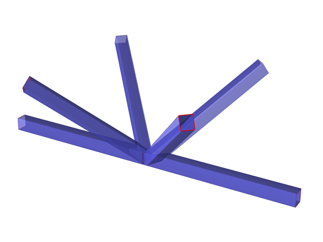
The Steel Joints add-on provides you with the option to connect circular hollow sections using welds.
It is possible to connect the circular sections to each other or to planar structural components. The fillets of standard and thin-walled sections can also be connected with a weld.
Go to Explanatory Video